 English
  Arabic
  Dutch
Dutch  French
  German
  Italian
  Portuguese
  Russian
  Spanish
 A screw can have the correct thread and still be the wrong length for an assembly. One buyer may report overall length while another reports length below the head. The difference becomes expensive when the screw bottoms in a blind hole, protrudes into a moving part or leaves too little usable thread.
This guide explains the measurement reference first, then shows how to turn a physical sample into an unambiguous OEM order. It covers screws for engineered assemblies; photographs illustrate product form and do not establish dimensions or tolerances.
1. Find the head’s seating reference before measuring
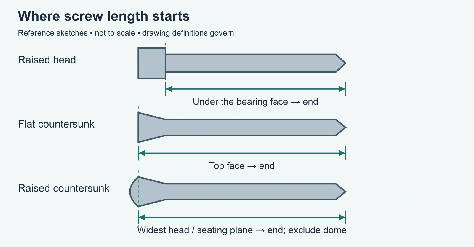
| Head or part form | Usual length reference | What to confirm |
|---|---|---|
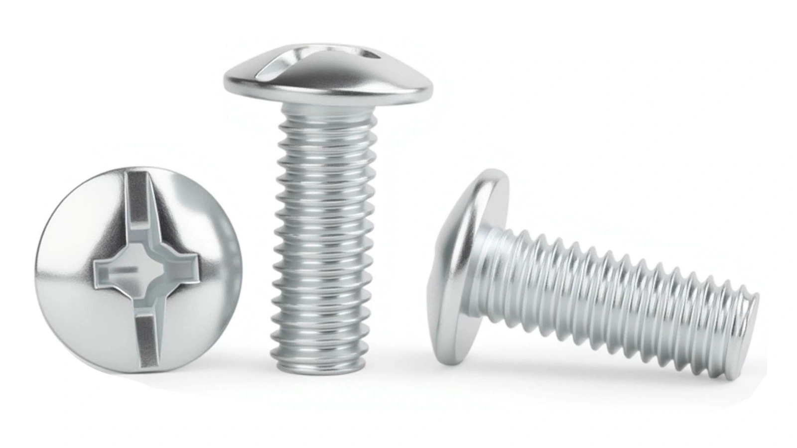
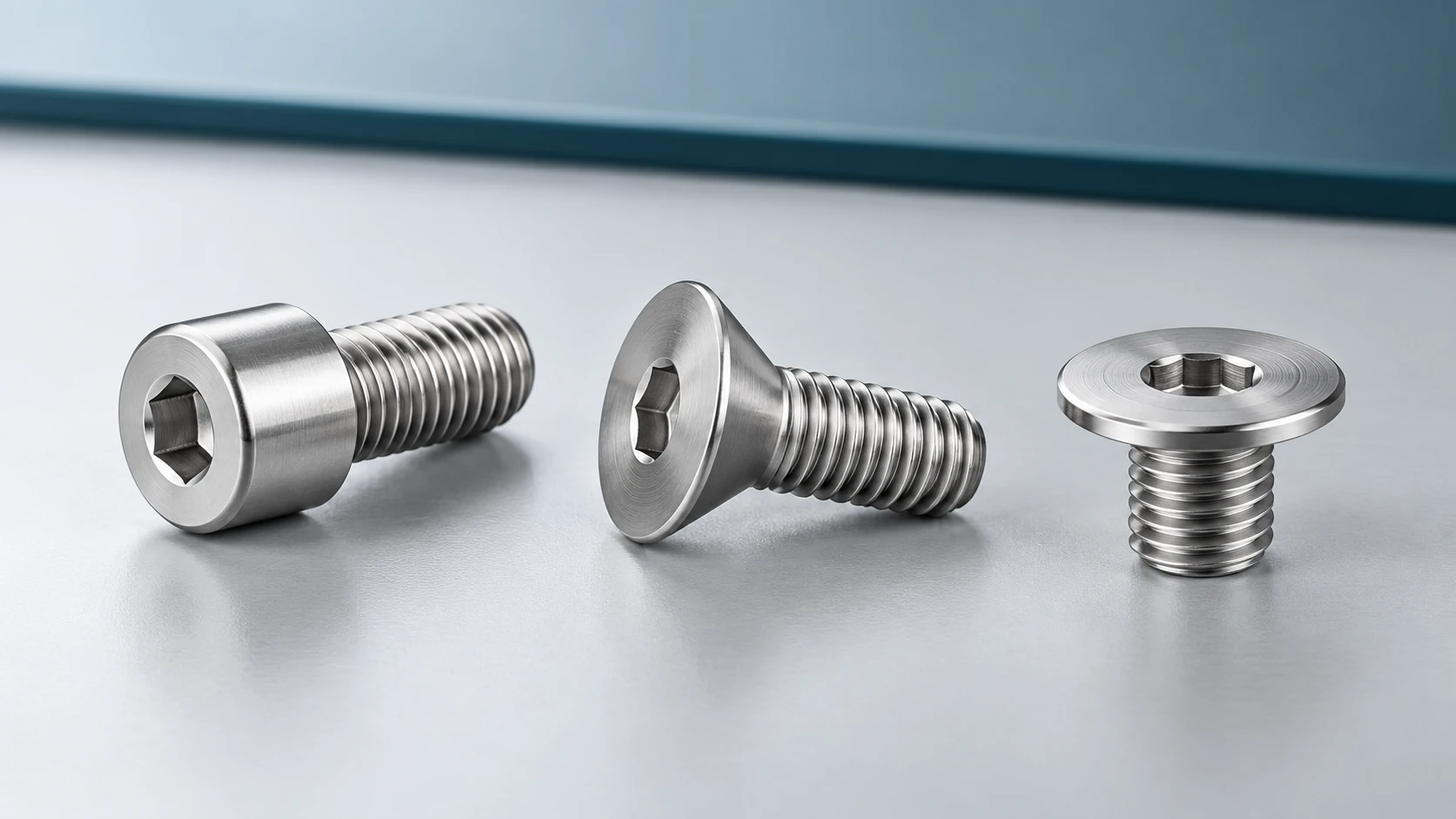
| Pan, socket cap, truss or another raised head | Underside bearing face to the end | Separate head height from nominal screw length. |
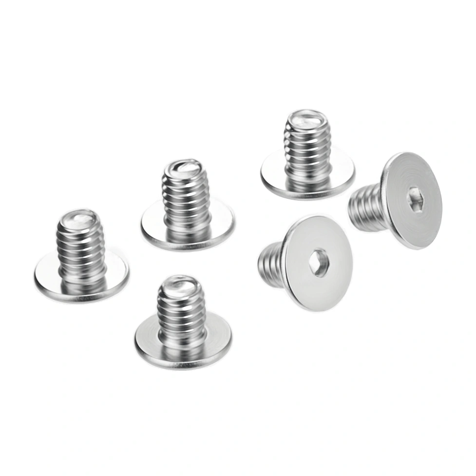
| Flat countersunk | Top of the head to the end | Confirm countersink geometry as well as length. |
| Raised countersunk / oval | Widest head plane to the end; dome excluded | Check the product standard or dimensioned drawing. |
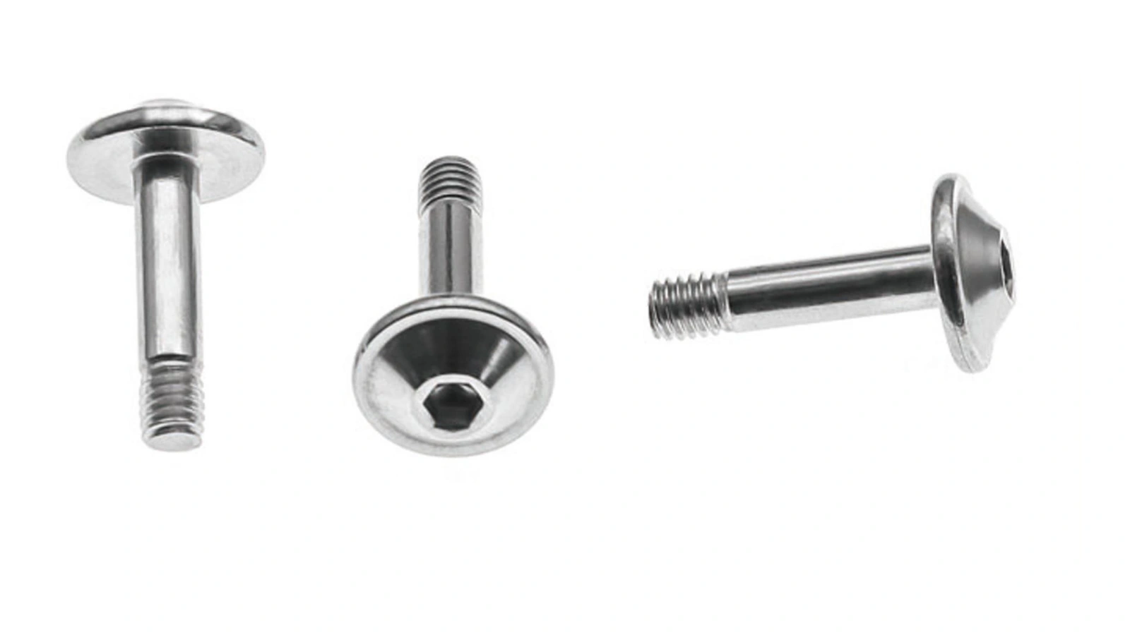
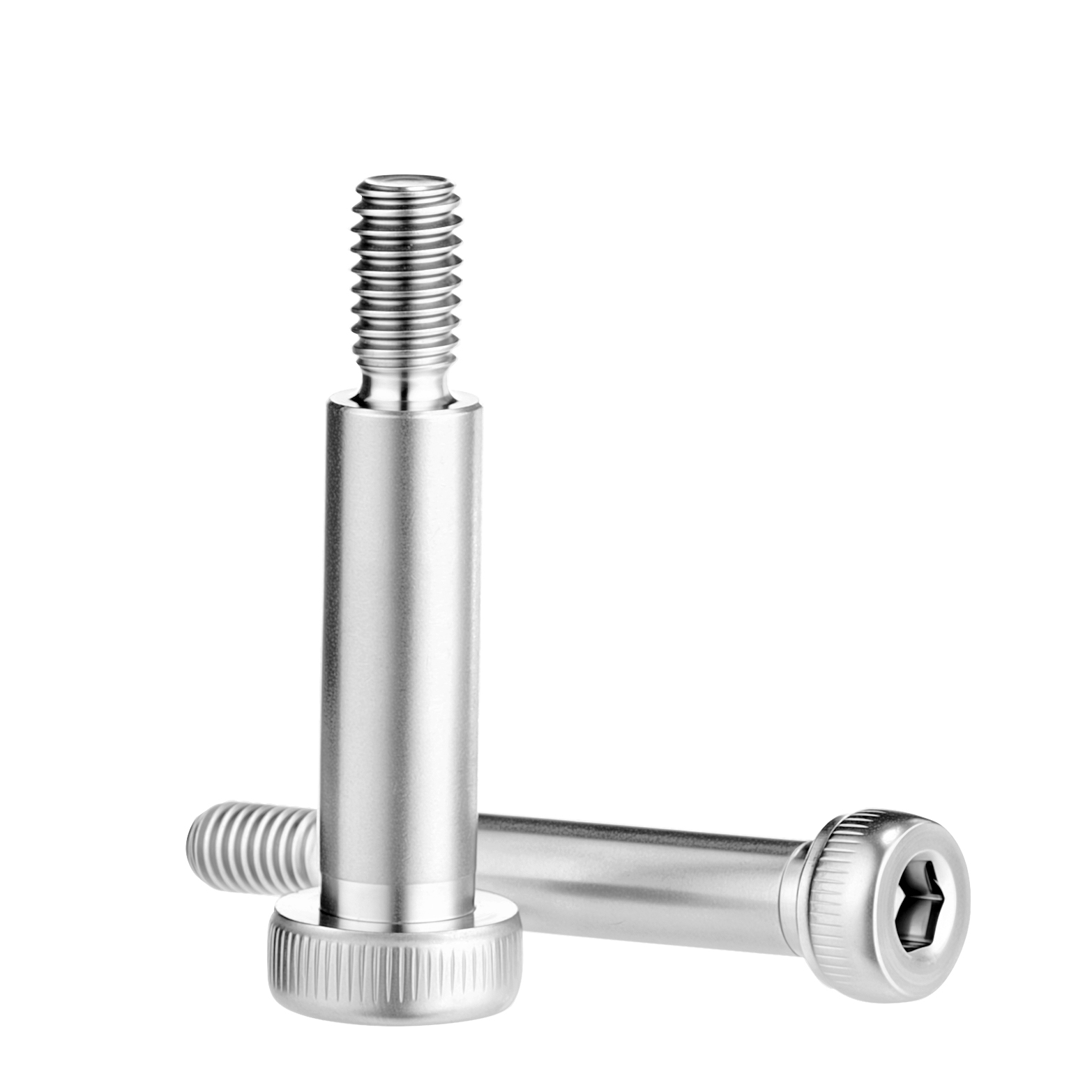
| Shoulder screw | Use the drawing’s shoulder and thread dimensions | Do not replace shoulder length with total length below the head. |
| Set screw / headless part | Usually end to end | Confirm point form and the defined dimension. |
These distinctions are consistent with Bolt Depot’s measuring guide and Accu’s screw measurement guide. The label “countersunk” alone is insufficient when a raised dome is present.
2. Measure a physical sample in a repeatable way
- Identify the screw form. Record whether the head is raised, flat countersunk, raised countersunk or a special design. A side-view photograph is useful, but a dimensioned drawing is better.
- Select a suitable tool. A ruler can screen a nominal length; use a suitable calibrated measuring instrument when checking a specified tolerance. Choose resolution and accuracy for the acceptance requirement.
- Check the measurement faces. Remove loose debris. A burr, damaged tip or plating buildup can change the reading. Do not grind a production part simply to obtain a favorable measurement.
- Align the part with the measuring axis. Seat the jaw against the defined head reference and the other jaw against the specified end. Avoid diagonal contact or measuring from the curved top of a raised head.
- Record the result with its definition. Write the unit, reference points, tool and drawing revision beside the reading. “Length checked” is not a usable inspection record.
When a tip is rounded, pointed or specially formed, its geometry also belongs in the specification. Two screws that share a nominal length may behave differently at the bottom of a blind hole.
3. Read M4 × 0.7 × 20 without mixing the dimensions
In a metric screw designation written as M4 × 0.7 × 20, M4 identifies a nominal 4 mm thread diameter, 0.7 identifies a 0.7 mm pitch and 20 identifies the nominal length in millimeters. The head type determines where that last dimension starts. It does not mean a measured thread crest must read exactly 4.000 mm, and it does not tell you the head height or the threaded length.
| Term | Meaning | Common mistake |
|---|---|---|
| Nominal screw length | The designated length using the head’s reference | Including a raised head in a below-head dimension. |
| Overall length | Physical end-to-end envelope | Ordering a raised-head part from its overall measurement. |
| Threaded length | Axial extent of the specified threaded portion | Assuming every nominally 20 mm screw is fully threaded. |
| Usable engagement | Thread engagement that can actually carry the joint’s load | Counting a tip, runout or incomplete thread as full engagement. |
4. Check the length against the assembly, not just the sample
For a raised-head screw, a useful preliminary geometry check is:
Nominal length below the head ≈ clamped stack + required insertion depth
Illustrative example: a 3 mm bracket, 2 mm spacer and 1 mm washer create a 6 mm stack. If an engineer specifies 8 mm insertion beyond that stack, the preliminary geometric length is 14 mm. This calculation is not a strength calculation or a recommendation that 8 mm is enough engagement. Available sizes, stack tolerances, entry chamfers, incomplete threads and bottom clearance still need review.
For a blind tapped hole, confirm the usable threaded depth rather than just the drilled depth. For a countersunk joint, use the drawing’s seating plane; do not automatically add the full head height to a stack calculation. A shoulder screw needs its own shoulder fit and thread engagement check.
5. Send a measurement record that a supplier can quote
An annotated drawing prevents repeated questions. When only a sample is available, include side and top views, a thread identification and a record like this:
| Field | Illustrative request — not a Hongyuan test result |
|---|---|
| Part identification | Raised-head hex-socket machine screw; internal part number and drawing revision. |
| Thread | M4 × 0.7; required thread tolerance specified on drawing. |
| Length definition | 20 mm nominal, underside bearing face to end. |
| Acceptance limits | Enter the actual drawing limits; do not assume a general tolerance. |
| Other dimensions | Head diameter/height, threaded length, tip form and clearance restrictions. |
| Commercial inputs | Material, finish, quantity, packaging and intended application. |
Frequently asked questions
Do I include the head when measuring screw length?
Include the head for a flat countersunk screw. Exclude a raised bearing head. A raised countersunk head normally excludes the dome above its seating reference, so use the relevant drawing or standard.
Can I identify pitch by measuring the screw’s length?
No. Pitch describes the axial spacing of adjacent threads. Use an appropriate thread gauge or another suitable identification method; length and pitch answer different questions.
Does a longer screw make a stronger joint?
Not automatically. A longer part can bottom out or interfere with adjacent components. Material, joint design, usable engagement and installation conditions govern the joint.
Can Hongyuan quote from a sample?
Send the sample information and application requirements for review. Any dimensions that remain uncertain should be resolved through the agreed drawing and sample approval before production.
Technical references
General guidance below is supported by these published references. The product drawing and order requirements govern the actual part.