 English
  Arabic
  Dutch
Dutch  French
  German
  Italian
  Portuguese
  Russian
  Spanish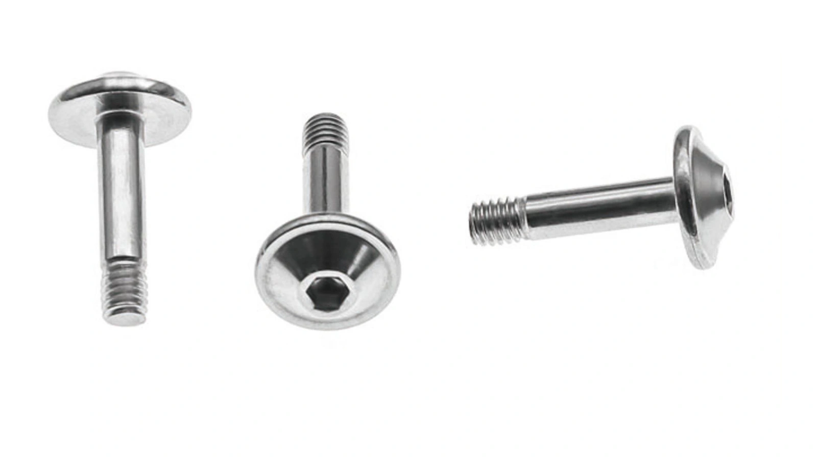
A screw can match the nominal thread size and still be the wrong length for a blind tapped hole. For industrial buyers, the useful drawing review is a three-part question: will the head seat, will enough usable thread overlap remain, and will the tip have the required clearance? This guide separates those questions and provides a geometry-only example that can be included in an OEM enquiry.
Why drilled depth is not thread engagement
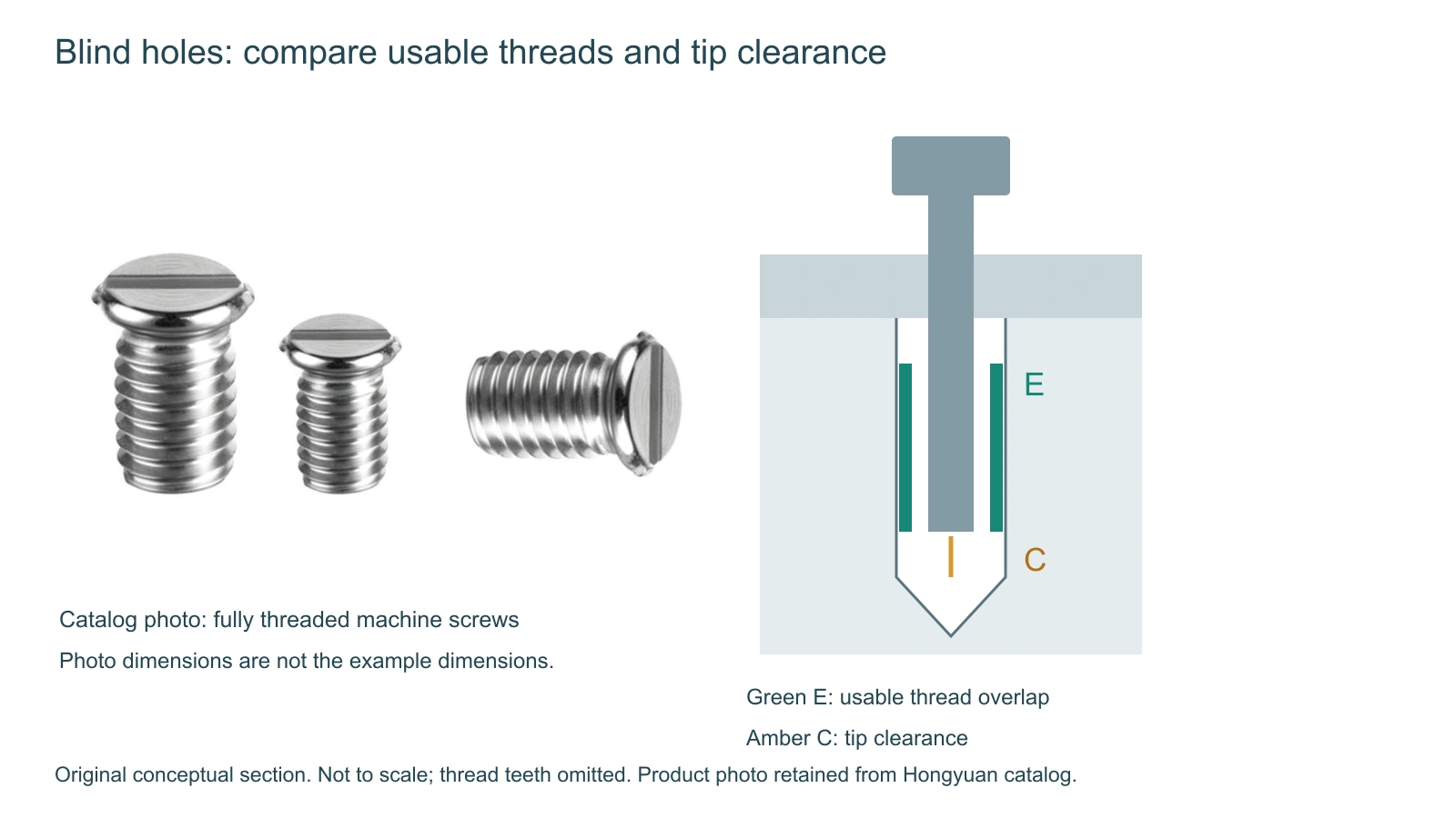
A blind hole terminates within a component. Its drawing may specify the drill depth, the full-thread depth and an entry chamfer separately. Those dimensions describe different features. The drill-point region and any incomplete internal threads must not silently be counted as a usable mating-thread length. The screw also has a tip or thread lead that needs its own allowance.
| Drawing item | Question it answers | Common review error |
|---|---|---|
| Screw length L | Where will the tip be after the head seats? | Mixing under-head and overall length definitions |
| Clamped stack S | How much length is outside the receiving component? | Leaving washers or a compressed gasket out of the stack |
| Usable internal thread zone | Where are full mating threads available? | Using total drilling depth as full-thread depth |
| Tip clearance C | Can the head seat before the tip interferes? | Treating a positive nominal clearance as a complete tolerance check |
Specify a common datum for the section view. For the simple non-countersunk example below, L is measured from the underside of the head and S from that same seating surface to the top of the receiving component. Countersunk screws require a different length reference, so the drawing must be adapted before using the arithmetic.
Required engagement depends on the receiving material
Bossard explains that minimum engaged lengths need definition when full load-bearing capacity is required, and that the receiving material strength matters. Its published recommendations also identify the screw class, thread tolerance and other conditions. A general ratio taken from a table is therefore not a universal minimum for every metal, screw or load case. Bossard technical overview and conditional recommendation table.
Ask the joint designer for the required usable engagement and its basis. Keep that requirement separate from the physical depth available. A drawing can provide enough space for the screw without establishing adequate resistance to thread stripping. Conversely, specifying a long screw to gain engagement can introduce bottoming or interference if the receiving feature is not changed.
A worked geometry check for an illustrative blind hole
The following numbers are invented teaching inputs, not Hongyuan product dimensions or a strength recommendation. Assume a fully threaded, non-countersunk screw, matching threads and an approved required overlap of 8.0 mm. The internal full-thread zone starts 1.0 mm below the receiving surface and ends at 11.0 mm. A 0.5 mm screw-tip allowance is excluded from the usable external thread.
| Input | Illustrative value | Meaning |
|---|---|---|
| L | 18.0 mm | Under-head screw length |
| S | 8.0 mm | Seated clamped stack |
| D | 12.0 mm | Assumed interference limit from the receiving surface |
| a / b | 1.0 / 11.0 mm | Start and end of usable internal thread zone |
| q | 0.5 mm | External tip region excluded from usable thread |
Tip penetration P = L − S = 18.0 − 8.0 = 10.0 mm. For this simplified fully threaded geometry, usable overlap E = max(0, min(b, P − q) − a) = min(11.0, 9.5) − 1.0 = 8.5 mm. Nominal tip clearance C = D − P = 12.0 − 10.0 = 2.0 mm. The example meets the assumed nominal overlap requirement, but says nothing about load capacity unless the design basis is valid.
For a clearance tolerance check, the deepest tip position is produced by the longest screw and smallest seated stack: Pmax = Lmax − Smin. Compare it with the smallest permitted interference-limit depth. For engagement, use the shortest screw, largest stack and least favorable usable-thread boundaries. A partially threaded screw requires a general overlap of two thread zones rather than the simplified formula above.
Turn the arithmetic into an assembly check
First confirm the part identities and drawing revisions. Then confirm that the head and any washer seat on the intended surface. Investigate unexpected resistance before increasing the tool setting. Finally, retain the inspection method and acceptance criteria approved for the joint. A dimensional depth measurement, a thread gauge and an assembly observation provide different information; one should not be described as proof of all three requirements.
What OEM buyers should send with an RFQ
| Enquiry field | Information to supply |
|---|---|
| Screw definition | Head, drive, thread designation, length datum, threaded length and tolerances |
| Receiving part | Section view, thread tolerance, material specification and usable-thread boundaries |
| Stack | All clamped parts and their seated minimum/maximum thickness |
| Joint requirements | Required engagement, tip clearance and the designer-approved installation criteria |
| Inspection | Drawing revision, proposed measurement/gauging method and requested records |
If only a sample is available, provide its mating component as well. Do not infer usable thread depth from the visible hole entrance. Explain whether the sample came from a new assembly or a used joint, and request review of the replacement drawing before ordering.
Frequently asked questions
Is one screw-diameter of engagement always sufficient?
No universal ratio is established here. Receiving material, screw properties and joint conditions must be included in the engineering basis.
Can I use drilled depth as the full-thread depth?
Only if the drawing actually defines them as equivalent for that feature. Otherwise keep the dimensions separate and identify the usable full-thread zone.
Does high tightening torque prove the head is seated?
No. Interference or binding can also create resistance. Check seating and investigate the source of resistance using the approved procedure.
Can the example formula be used for a shoulder screw?
Not directly. A shoulder or unthreaded shank changes the external thread zone; calculate the overlap of the actual usable internal and external regions.
Review the mating hole with Hongyuan
Send the screw drawing, the receiving-part section and the seated stack with your enquiry. Request confirmation of the proposed part definition and the requirements that can be evaluated. Resolve the joint design and acceptance criteria before treating a length substitution as interchangeable.
Related reading: How to Measure Screw Length. Contact Hongyuan with your drawing and purchasing requirements.