 English
  Arabic
  Dutch
Dutch  French
  German
  Italian
  Portuguese
  Russian
  Spanish
 A pin can look like the simplest component in an assembly—and still decide whether a joint aligns, moves freely or comes apart for servicing. For custom pins, the important question is not just “What diameter and length do we need?” It is “What must this pin do once it is inside the product?”
A locating pin, a pivot pin and a removable retaining pin may all have a smooth cylindrical body. Their fit, shoulder positions and retention details serve different purposes. Understanding those differences helps OEM buyers develop a part that suits the complete joint, rather than ordering a familiar-looking shape and solving assembly problems later.
Start with the job, not the silhouette
Before choosing a pin style, identify which components must stay fixed and which must move. A pin that locates two parts during assembly has a different job from one that forms the axis of a repeatedly moving linkage. A service pin must also be accessible after surrounding parts are installed.
| Function in the assembly | What matters most | Design question to resolve |
|---|---|---|
| Locate two components | Position of the mating holes and the fit at each interface | Which component retains the pin, and which component must slide over it? |
| Provide a pivot | Working diameter, bearing length and freedom of movement | Where should rotation occur, and how will wear be managed? |
| Connect parts that need removal | Insertion access, grip and axial retention | How will the operator release and withdraw the pin? |
| Establish a stop or spacing feature | Shoulder position and the contacting faces | Does the shoulder locate a part, limit travel or leave a deliberate gap? |
This functional description is particularly useful when replacing an existing pin. Copying the visible outside dimensions may overlook the bore fit or the contact surface that actually controls the mechanism.
Three details that give a stepped custom pin its purpose
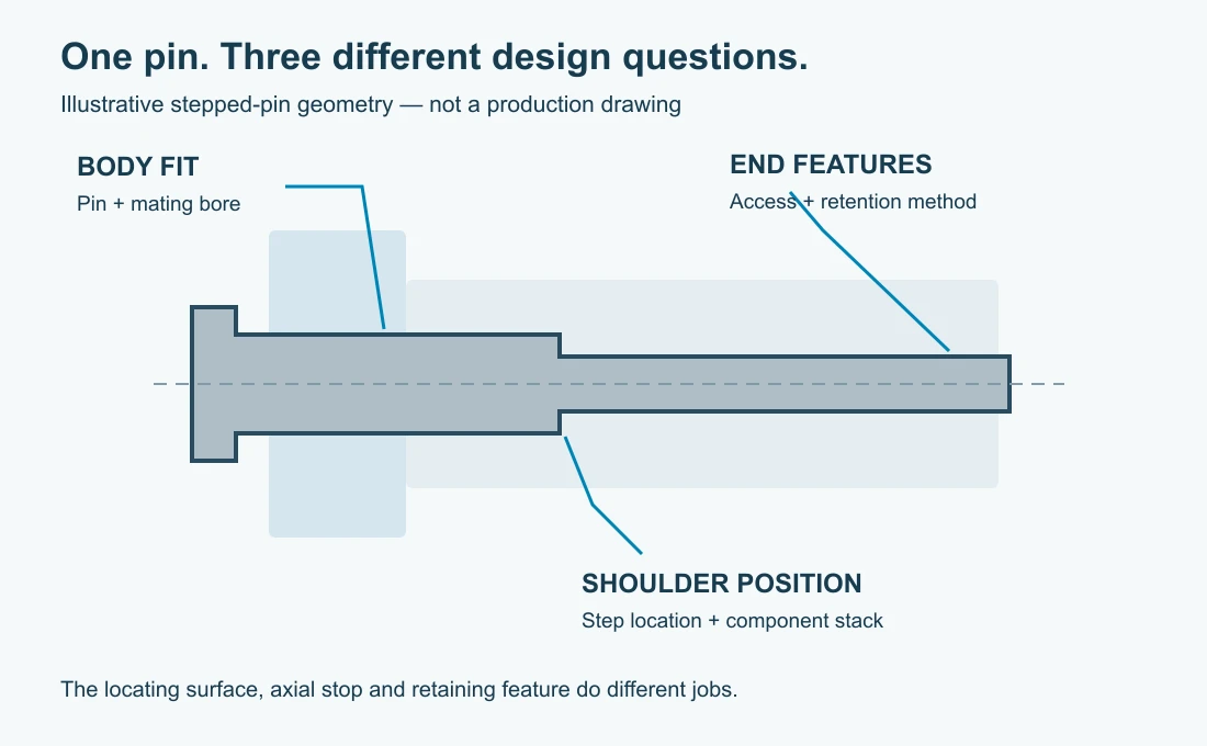
Custom Pin Body Diameter and the Mating Bore
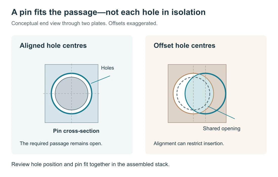
“A tight fit” is not a complete specification. The pin and mating hole tolerances together determine whether the joint has clearance or interference. If a pin passes through several parts, hole alignment also matters: a pin can fit each individual hole and still be difficult to insert through the assembled stack.
For a pivot, identify the surface intended to move against the pin. For a locating arrangement, identify the fixed side and the removable side. These decisions guide the fit requirements; there is no single pin tolerance that suits both jobs.
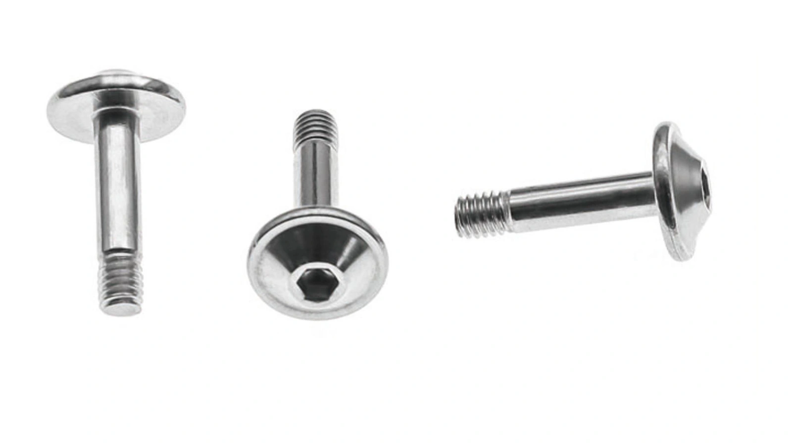
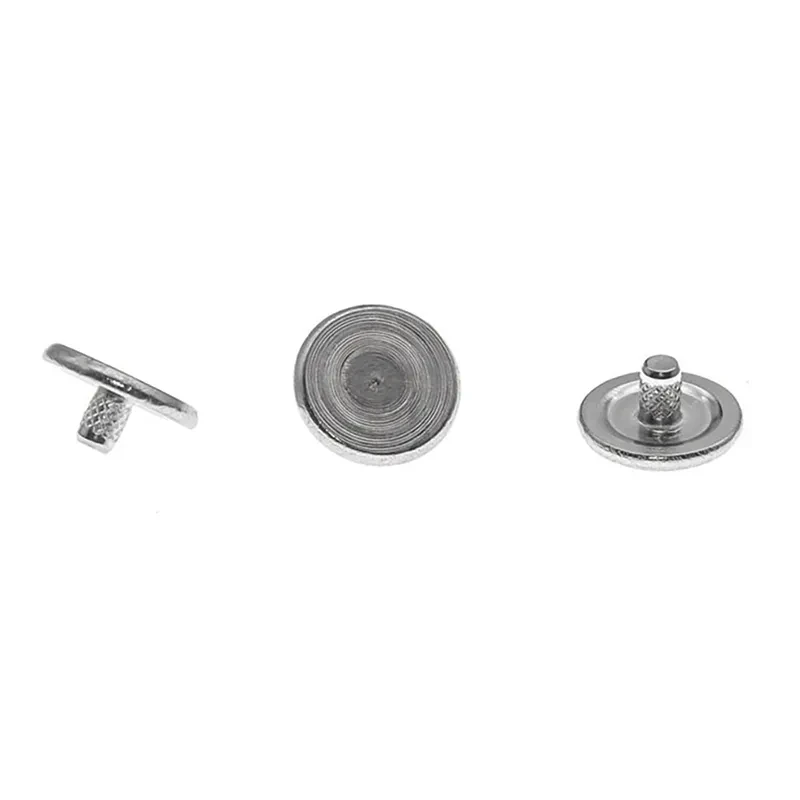
Look at the surface that meets the hole. The short, locally knurled shank below has a different surface geometry from a smooth locating pin. Identify which section is meant to contact the mating component before defining its fit. A textured section should not be substituted for a smooth pivot surface simply because the outside dimensions look similar.
The shoulder is a functional face
A diameter step can provide a positive stop or separate two working portions of the pin. Its axial position should therefore be related to the component stack—not specified only as an attractive proportion on the drawing. Too little working length can restrict motion; too much can leave unwanted end play.
The transition also needs attention. A fillet at the shoulder may contact the edge of a mating hole before the flat shoulder face seats. Review the corner geometry and any matching relief as a pair rather than treating them as unrelated dimensions.
Retention must match the service routine
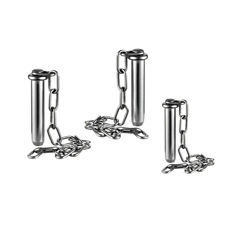
A head can stop movement in one direction, but it does not automatically stop withdrawal in the other. A joint may use a retaining ring, cross-pin, thread or another approved feature. The correct arrangement depends on access, loads and whether removal is occasional or frequent.
A tether chain has another role: keeping a removable component nearby. In the headed furniture pin example, it should not be mistaken for a rated load-carrying connection or proof that the installed pin is locked. The retention function must be considered separately.
A shoulder screw is not simply another name for a pin
Both can present a smooth cylindrical surface to a mating component. The difference becomes clearer at the ends. A shoulder screw has a threaded fastening portion and a drive feature; an unthreaded pin needs a different means of being held in the joint.
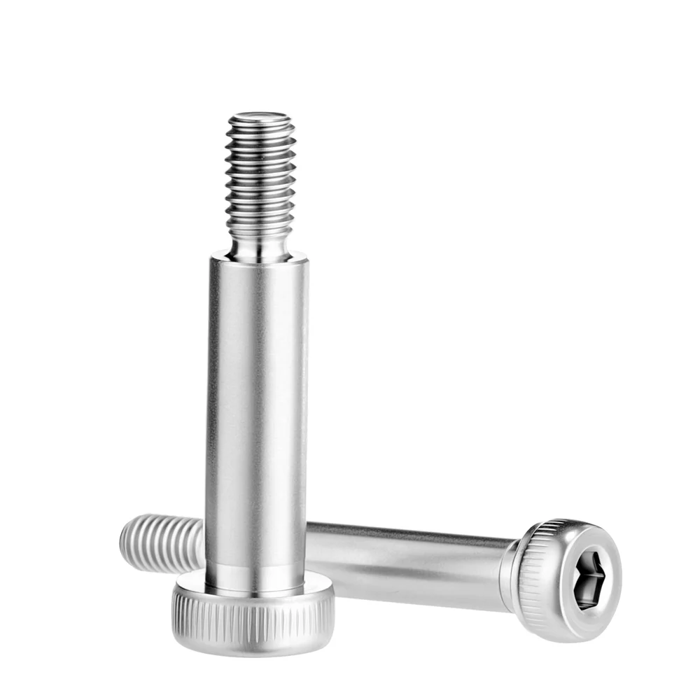
If the design needs a smooth bearing surface with threaded installation, a shoulder screw may be worth reviewing. If it needs quick withdrawal without unscrewing a fastener, a removable pin arrangement may be more appropriate. The choice should follow the assembly and maintenance method, not appearance alone.
When a pin fits the drawing but the joint does not work
An assembly review can reveal problems that isolated diameter measurements miss. The following observations help direct the discussion; they are starting points for investigation, not diagnoses by themselves.
| Assembly observation | Features to review together |
|---|---|
| The pin enters one part but not the complete joint | Hole position, alignment, accumulated tolerances and insertion direction |
| The mechanism binds after assembly | Working length, shoulder contact, bearing clearance and the retaining arrangement |
| There is excessive axial movement | Component stack, shoulder location and the spacing of retaining features |
| The pin is difficult to remove during service | Tool or finger access, end grip, contamination and wear at the working surfaces |
| The pin moves out of position | The actual axial restraint; a head or tether alone may not provide the required retention |
Material selection belongs in the same discussion. Corrosion exposure, contact pressure, wear and the mating material can lead to different requirements. A stainless designation alone does not establish hardness or wear performance; specify the required material condition and surface treatment where they affect function.
Frequently Asked Questions about Custom Pins
Can one custom pin both locate and pivot?
It can perform more than one function, but each interface must be defined. Decide where the pin is fixed and where movement is permitted, then specify the associated fit and working length separately.
Should every dimension have a tight tolerance?
No. Give particular attention to the features that control position, movement and retention. Other dimensions should have tolerances appropriate to their role. Unnecessarily restrictive requirements can add manufacturing and inspection effort without improving the joint.
Is a loose sample enough to develop a replacement?
A sample helps describe the shape, but the mating components or an assembly drawing explain how it functions. Worn areas may no longer represent the intended dimensions, so identify the working surfaces before using the sample as a dimensional reference.
Develop the Custom Pin Around Your Assembly
Hongyuan’s custom fastener discussion can start with the joint itself: what must align, what must move and how the connection is serviced. Share the assembly view alongside the pin drawing so the body, shoulders and retention features can be reviewed as one system. Contact Hongyuan to discuss a custom pin for your application.